ABSTRACT
Climatic change is manifested in a number of places by significantly spatially localized torrential rainfall with a short duration, but with great intensity. One of the expected consequences of this type of precipitation is the occurrence of flash floods, characterized by a sharp rise from the value of the normal flow to the value of the peak flow and a rapid decrease again. The consequence of this type of short episodic floods is the initiation of morphological transformations in the beds of smaller and medium upland streams, often with devastating effects for the section of the watercourse channel. The article summarizes research on the formation and development of a scour hole in the section at the transition from a lined riverbed with fixed bed and banks to the riverbed with loose channel boundry which can be transformed morphologically in an uncontrolled manner. In this research, the main attention was paid to the formulation of a parametric model of the scour hole morphological development at the transition between a lined and an unlined channel. The results of this model can be used both to understand the hydraulic-morphological processes that occur at the site of a sudden river bed change, and for the practical design of restoration modifications to the river bed at the transition from a fully lined to an unlined river bed without any protective measures, approaching the original pristine conditions.
INTRODUCTION
Riverbed restoration is one of the adaptation measures in the field of reducing the impact of drought on the water regime in the landscape. These adaptation measures are among the main topics of the research activity of the project SS02030027 „Water systems and water management in the Czech Republic in conditions of climate change (Water Centre)“. This is mainly the area of draft measures leading to the reduction of flood risks with a focus on aspects of the influence of climate change on floods. This also includes research into the impact of climate change on ecosystems and the reduction of the consequences of anthropogenic influence on aquatic and water-related environments and the creation of conditions for improving protection of ecosystems. Nowadays, watercourse channel restoration is perceived on a narrower hydromorphological scale as a set of measures that enable the formation of a channel in the presence of a wide spectrum of channel-forming, primarily fluvial, processes. These processes also include the creation of hydraulic current structures in watercourse channels – for example, current contraction and expansion, the formation of wakes with the presence of vortices with a vertical axis, and the formation of a hole with a horizontal axis as part of a hydraulic jump. Furthermore, erosion, transport and sedimentation processes arise, which are linked to the previous hydraulic phenomena. They depend on the geomechanical properties of the material in which the channel is transformed and on the stability of the banks, which with their malleability significantly contribute to the variable geometry of the channel. When designing restoration modifications, it is advisable to base it on knowledge and observations of successional processes involved in the channel transformation. Significant morphological changes can be observed in field conditions during flash floods and after them, where morphological changes have a significantly accelerated course. Furthermore, morphological changes can be observed during targeted physical research in laboratory conditions, in which the process can be monitored and evaluated in more detail, but should, if possible, be verified for conditions that are as close as possible to real river channels. In this paper, the author focuses on the creation and development of a 3D scour, often called a „pear“ due to its characteristic shape, which is created at the transition between a lined and open channel. This also corresponds to the restoration of watercourses in the past, marked by continuous amelioration, during which lining was removed in entire sections of a channel.
Investigation of a scour hole in the transition zone of an open channel
The issue of stabilization of an open channel in its expansion has already been dealt with by a number of authors, e.g. [3, 7]. Research at WRI Bratislava [3], which in its character was probably closest to this 3D scour hole study, was the first to adopt the working designation „pear“ for this morphological object on a watercourse (Fig. 1 right). Although the research was carried out on a model of a „pear“ type in several shape alternatives (including taking into account the influence of sediment transport from the upper parts of a watercourse), hydrotechnical methodology was not given, just general recommendations for the construction of these objects.
The author‘s own research project, dealing with morphological changes in small, relatively steep upland streams under high flows, was carried out in two stages:
- Field investigation with monitoring the river channels‘ reaction to natural or artificially induced morphological changes. The aim of this stage was to perform a qualitative description of the changes.
- Laboratory model experiments, which were focused on the design of a quantitative model of morphological transformations with the ability to predict the morphological response of the river channel when using environmentally friendly and cost-effective restoration measures.
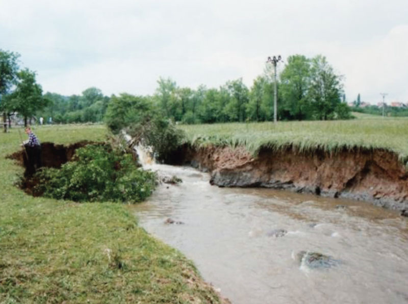
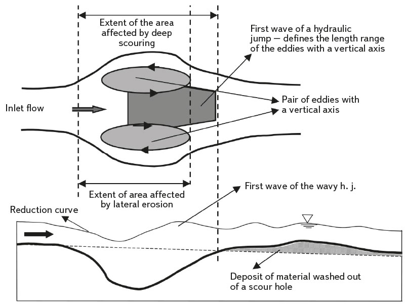
Fig. 1. Development of the „pear shaped“ scour resulting from degradation of a drop structure on flash flood (left); feature of flow in transitional zone of the spatial 3D scour (right)
In a part of the project with the aim of enabling the quantification of morphological changes, systematic research was carried out in laboratory conditions on two different types of channel model in the transition zone. For a more complex description of the model behaviour, a „complete 3D“ model of the river channel in the transition zone of its opening was chosen (Fig. 2 left). In order to speed up the process of documentation of the immediate development of the scour hole depression of the river channel, a model of a symmetrically simplified „half“ river channel was designed (Fig. 2 right). The axis of channel symmetry was the glass wall of the hydraulic channel, in which the channel was created in the entrance lined part and the transition open part. This second model made it possible to capture the course of the water level and river bed very quickly in the longitudinal direction almost immediately. To speed up geometric alignment of the water level and river bed, optical accessibility through the glass side wall of the channel was used. It was also possible to measure the velocity fields in the transition zone of the river channel significantly faster than with the complete 3D model of the river channel. It is obvious that the assumption of symmetry was also a simplifying assumption from the point of view of the real development of the river channel in the opening, which had to be verified in the next phase of the project with a complete 3D river channel model. In principle, there should be no objective reasons for significantly asymmetric scour hole development, unless special conditions are created. Further details of the research are described in the literature [5, 6] and are not presented here for brevity.
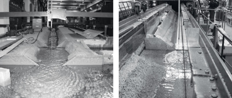
Fig. 2. Full space model of the channel in the transition zone of scour hole development (left); symmetric half-space model of the channel with axis at the flume glass wall (right) – all under laboratory conditions
Scour hole development in a complete channel model
Based on the observation of the successive development of the 3D scour hole in non-cohesive materials, partial findings can be summarized as this (see diagram in Fig. 1 right):
- At the transition from channel section with a fixed boundary to section with a loose boundary, the whole process begins with the formation of a small erosive hole in the bed, as also happens with wide channels. When a sill is spontaneously formed in the bed at the transition between the channels, a flow with the character of a hydraulic jump arises. At first, it is a flow with an undular or weak hydraulic jump.
- As the depth of the bed depression increases, this flow in the longitudinal level does not significantly change its character. As soon as the bed depression reaches the foot of the slopes, their stability is disturbed and small parts or even whole blocks of material start to slide into the depression. The slopes of the changing channel near their foot no longer smoothly follow the slopes of the lined channel. Here, the current breaks away from the wall and the first lateral vortices are formed at the foot of both slopes.
- Lateral vortices begin to gradually grow and become stronger. They get the majority of their circulation energy from the main stream near the channel axis. The side holes expand from both sides, compressing the central stream and leading to its lateral contraction. This multiplies its tangential shear effect at the bed, and from this moment the deepening of the scour hole proceeds very quickly.
- The more the scour hole extends to the sides, the more developed the circulation structure of the side holes is. The sand material, carried from the bed by strong current of the hydraulic jump near the longitudinal axis of the channel, is partly carried away from the scour hole area and partly circulated in the side holes. The movement of individual sand particles in the circulation areas takes place from the centre of the stream to the sides towards the slopes; from here along the side slopes it is sucked upstream and back into the main stream in the channel axis.
- Once this circulating sediment process stabilizes, further development of the maximum scour hole depth begins to slow down. The main stream already has a partially exhausted transport capacity with the material that is circulated in the side holes. This material re-enters the main stream whenever the flow in the side holes moves it at the bottom to the channel axis.
Sometimes the width of the side holes becomes too large for the back-current along the slopes to have sufficient force to remove the material from the bed. The scour hole deepens more near the centre; at the edges it deepens less or not at all. In such cases, the bed at the edges of the scour hole depression is very flat, and at the centre of the channel it slopes steeply to the point of maximum depth of the scour hole. Some kind of side platforms are created here with one narrow deep bed hole in the middle of the profile.
Hydraulic basics of scour hole study
Since a hydraulic jump occurs in the place of a 3D scour hole, the characteristics of which can be obtained by applying momentum theorem, it is quite natural to consider that the model of a 3D scour hole will also be based on this principle. Momentum theorem allows an exact solution when designing the dimensions of constant-width apron in weir, but for the case of a „pear“ 3D scour hole the width is variable. It is also necessary to take into account the normal pressure force, which is the reaction of the walls of the „pear“ object, although in the case of deformable banks this does not apply either. In plan view, the dimension of the hydraulic jump from the sides is not defined by solid walls, but by the interfaces with the lateral votices (Fig. 1 right). Due to the fact that the water has a peripheral velocity at the interface with lateral vortices with vertical axis, which is determined by the intensity of the flow circulation in the vortex, it is necessary to calculate not only the magnitude of the normal force, but also the tangential shear force. In addition, the distribution of pressures in the inlet profile may not always be hydrostatic, and the momentum of the flow in the outlet profile is also affected by the size of the Boussinesq number (the ratio of the actual momentum of the flow to the momentum expressed from the cross-sectional velocity) due to the non-uniform distribution of velocities in the cross section profile. It is clear from the above that a simple application of momentum theorem does not achieve the objective. The author‘s proposal appears to be more promising; following the example of Hunzinger [4], he makes the dimensionless length of the wake in wide channel section:
and the parameter F of the kinetic to potential energy exchange due to flow expansion (Eq. 2).
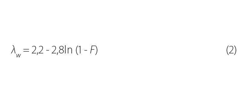
(2)
The dimensionless parameter F was defined by Ashida [1] by the following relationship:
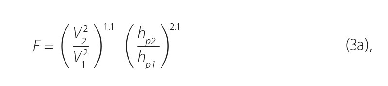
which is an expression of the energy exchange in the transition zone between the input profile 1, where the original width of the channel is unchanged, and profile 2 where, in contrast, the width of the scour hole to the sides is the largest. The reason why the energy exchange parameter F could be a good indicator of the tendency to create a „pear“ 3D scour hole stems from the consideration that the more fluid‘s energy (kinetic and potential) is converted in the balance cross section into a dissipative form of energy and into a part of the energy applied during the transport of river channel bed and banks material, one can expect greater transformative effects of the current on the channel morphology, and thus a greater spatial extent of the created scour hole. All quantities appearing in relationship (Eq. 3a) are shown in Fig. 3. In this diagram, the meaning of the given values is as follows:
V1, V2 [m.s-1] – cross-sectional velocities in the respective profile
A1, A2 [m2] – flow areas in the relevant balance profile
c .A2 [m2] – part of the flow area in profile 2, reduced by the recirculation area of the lateral vortices
H1 [m] – flow depth in balance input profile 1
hp1, hp2 [m] – water stage at the entrance to the scour hole and in the scour hole respectively, measured from the lowest level of the bottom of the scour hole
∆HP = hp1 – hp2 [m] – difference in the water stages in the balance profiles
Ys [m] – „pear“ scour hole depth
Lw [m] – total „pear“ scour hole length
B1, B2, B3 [m] – stream widths at the surface at the entrance to the scour hole, in the scour hole, and just behind the scour hole
In Eq. 3a, however, a single cross-sectional velocity is considered in the entire profile 1 and 2. Based on the author own research on the distribution of point velocities in the transition zone of scour hole development [5], it is recommended to modify the cross-sectional velocity elements in profiles 1 and 2 with the respective profile kinetic energy coefficients (Coriolis number αe), including the ratio of the actual kinetic energy height to the energy height expressed from the mean cross-sectional velocity.
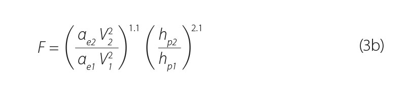
In the balance relationship (Eq. 3b), special care must be taken to choose the appropriate position of both balance profiles – especially profile 2 (Fig. 3).
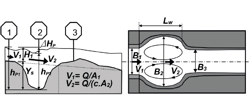
Fig. 3. Typical form of the “pear” shaped scour hole in a long section (left) and a plan view (right) with basic dimensions marked at characteristic profiles of scour hole
Methodology for determining channel changes
The main goal of this paper is to propose, based on previous observations [5, 6], a simple procedure for determining the dimensions of a 3D scour hole, which occurs at the transition from a lined channel section with fixed boundary to a channel with completely loose boundary without any technical support. The procedure should be as simple as possible, making it possible to determine the extent of morphological changes in the river channel without the need to know too many details, which can mostly only be determined in laboratory conditions.
Relationships for determining the basic dimensions of a 3D scour hole
The measurement procedure on the „full“ 3D model was very slow and tedious. It was not possible to measure the corresponding time courses of the water level and the bottom in the longitudinal profile and in both balance cross profiles. For systematic measurement, it was therefore necessary to limit access to a half channel. All evaluated experimental data in the graphs in Fig. 4 come from these measurements.
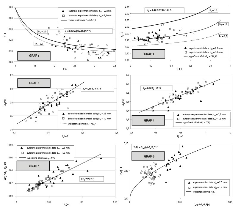
Fig. 4. Relationships derived to design a preformed scour hole at a channel transition; Graphs 1–6 are referred in the flow chart of design procedure of the scour hole (Fig. 6)
It is not very practical for a river engineer to use a formula in the form of Eq. 3b, for example due to a lack of knowledge about the distribution of local velocities in profile 1 and especially 2 (Fig. 3), where the lateral vortices arise. Some alternate, more straightforward relationships need to be used. The relationship between F a β = B2/B1 plotted in Fig. 4 (Graph 1) is presented. It is clear that F is not only a function of the geometric dimensions of the scour hole, but is also related to the properties of the flow before entering the changing channel. Therefore, the following relationship is proposed: F = F(β, Fr1), where Fr1 is the Froude number of the flow in the inlet section 1 defined by the relationship Fr1 = V1/(gH1str )0.5, where H1str is the mean flow depth H1str = A1/B1, A1 is the flow area in the balance profile 1 and B1 is the width of the surface flow in the same section. An exponential relationship (Eq. 4) was derived, which naturally fulfils the logical condition F = 1 for the channel widening ratio β = B2/B1 = 1.
The relationship obtained by interpolating experimentally determined points reaches the coefficient of determination R2 = 0.867.
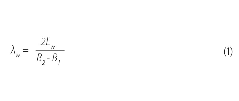
Furthermore, the relationship between the dimensionless flood length λw was obtained from the experimental data (Fig. 4 – Graph 2) in analogy with Hunziger relationship (Eq. 2). The relationship takes into account the dependence of the geometric dimensions, participating in the expression of the dimensionless quantity λw, on the energy conversion parameter between profiles 1 and 2, and also takes into account the conditions (Fr1) at the inlet flow to the transition zone of the channel, where the scour hole develops.
λw = 1.47-0.65ln (1-F) Fr1 (R2 = 0.978 – see Fig. 4 – Graph 2) (5)
Experience from research into the shape a scour hole, which is created by the effect of a submerged horizontal jet on a deformable bed [2], shows that the shape of a scour hole at individual moments of its development is similar – affine (Fig. 5). An obvious similarity between the observed shape of the surface and the bed in the longitudinal profile can also be detected (Fig. 1 right). Therefore, it is necessary to look for relationships between the basic geometric parameters of the scour hole (B2, B3, Lw, and Ys) and also between the levels of the water level (∆Hp = hp1 – hp2) and the bed (Ys). Other derived relationships (Eq. 6, 7, 8) drawn from experimentally obtained data (Fig. 4 – Graphs 3, 4, 5) were again determined using statistical analysis [5, 6].
B2 = 1.58Lw + 0.14 (R2 = 0.992 – see Fig. 4 – Graph 3) (6)
B3 = 0.58B2 + 0.10 (R2 = 0.978 – see Fig. 4 – Graph 4) (7)
∆Hp = 0.51Ys (R2 = 0.923 – see Fig. 4 – Graph 5) (8)
The last statistically derived relationship from the experimentally obtained data on the “half” model of the open channel can be seen in Fig. 4 – Graph 6.
The author is aware of the fact that Eq. 9 can also have a different form than the one presented here, with the representation of a number of other combinations of dimensionless quantities. According to [6], from the whole range of verified relationships between dimensionless quantities, the form presented above was selected based on the best achieved criterion value of the optimization process (R2) when including the minimum number of parameters intended for optimization (only the power exponent), which had a positive effect on the small error in their value. This equation mutually binds all three main parameters of scour hole geometry Lw, B2, Ys with the quantity B1 at the entrance to the scour hole depending on the geomechanical properties of the soil (tg φ [-], d50 [m]).
In addition to the definition equation of the energy conversion parameter (Eq. 3a) and the proposed empirical equations (Eq. 4–9), in accordance with Fig. 3, the basic coupling equations for water stages (potential heights in balance profiles 1 and 2) can also be derived.
hp1 = Ys + H1 (10)
hp2 = Ys + H1 – ∆Hp (11)
The last coupling equation serves to express the dimensionless length of the wake λw, where Lw is the length of the wake corresponding approximately to the length of the scour hole.
All the necessary quantitative relationships were derived for the design of the dimensions of the morphological object. All relationships are dimensionally homogeneous; they are presented in the form of dependence of the geometric dimensions of the scour hole (Eq. 6, 7, 8, 10, 11) or dependence of dimensionless parameters (Eq. 3a, 4, 5, 9, 12). Input data for these formulas are the main geometrical and hydraulic characteristics of the inlet flow (B1, H1, V1, Fr1) in the section of the river channel before the opening of the stream and the geomechanical properties of the non-cohesive material in the open part (angle of repose of the soil under water φ and representative soil grain size d50). It should be noted that, in the case of applying experimentally derived equations, it is necessary to assume the validity of these relations for a certain range of dimensionless parameters used. Dimensionless relations (Eq. 4, 5, 9) were derived in the range of the Fr1 parameter (0.75; 1.9) – i.e., rather in conditions characteristic of upland to mountain streams. The channel expansion ratio β = B2/B1 in the scour hole in the experiments corresponded to the range (1.8; 3.5); i.e., flow conditions with well to very well developed lateral vortices, which significantly participate in the formation of a 3D scour hole with the characteristic “pear” shape. Dimensionless scour hole parameters were in this range: B2/H1str (15; 50),
Lw/H1str (7; 23), and Ys/H1str (0.6; 2.7). The energy conversion parameter F was in the range (0.04; 0.8). The experiments were conducted only on two types of granular non-cohesive bed, formed by significantly uniform-grained sharp-edged silica sands FP 1–1.6 and FP 1.6–4 mm with grain d50 = 1.3 mm and 2.5 mm, and with inhomogeneity numbers U = d60/d10 1.5 and 1.7, respectively. The specific weight of the sand was 2,516 kg/m3 and the volume weight 1,560 and 1,600 kg/m3 for both cases. The angle of repose under water was 33.8° for finer-grained sand and 35.9° for coarser sand.
Changes of all relevant geometric dimensions, which are associated with the formation and development of a scour hole, are dependent on the parameter, which is time – we can therefore speak of a “parametric scour hole” [2]. In the case of designing a “pear” scour hole as a stabilized scour hole, it is necessary to start from one known dimension of the scour hole. In practice, a frequent restriction for the design of a “pear” scour hole is the limited width of the adjacent bank, where it is not necessary to solve complicated relationships with the owners of the surrounding land. Therefore, this limited dimension will be chosen, corresponding to the quantity B2; however, it is possible to choose any of the other dimensions (Ys, Lw). With this option, the time factor is indirectly introduced into the calculation. The designer of a “pear” shaped scour hole does not need to know how much time t it would take to create a scour hole of the calculated dimensions. What is essential is the fact that the dimension of the chosen scour hole (variable at time t) is a limit beyond which it is no longer possible to go, and that the shape of the scour hole corresponds to one of the affine intermediate states (Fig. 5), corresponding to the current extent of a pair of vertical water holes. The “pear” scour hole must then be stabilized in the dimensions determined by the calculation, for example with embedded lined ribs in the bed and on the slopes at the beginning and end of the scour hole. However, specific technical measures for the stabilization of scour holes must be based on common local practice on the given watercourse, respecting in particular the character of the soils in the alluvial deposits and the available material base.
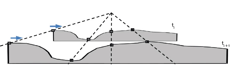
Fig. 5. Parametric scour hole development – the scour hole shape for any time instant t is affine to the shape at another time instant t + 1
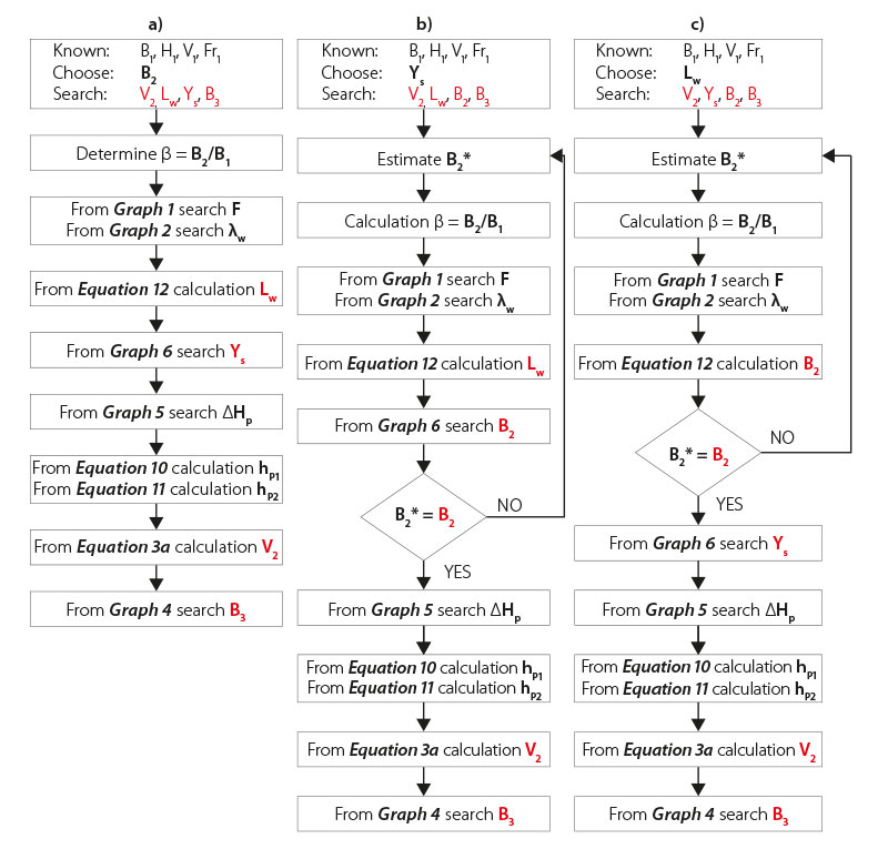
Fig. 6. Flow chart of design procedure of the 3D scour hole where one dimension is chosen: a) B2 is given; b) Ys is given; c) Lw is given. The referenced graphs are shown in Fig. 4; the numbers of the referenced formulas correspond to the text
3D scour hole design methodology
The procedure for determining the basic dimensions of the scour hole in the transition zone of the open river channel is based on Fig. 6. For the inlet shape-fixed profile 1 of the lined river channel, the following flow characteristics are known: depth H1, velocity V1, value of the Froude number Fr1, and width of the flow B1 corresponding to the initial width of the channel in the transition area of the open channel. The design of the scour hole as a spatial morphological element consists in determining its basic geometric dimensions B2, Lw, Ys, B3, and determining the reduced cross-sectional velocity V2 in the extended profile 2 (Fig. 3). The procedure for determining the basic dimensions of the scour hole differs for alternatives a), b) or c) in Fig. 6, depending on whether the initial known or specified dimension of the scour hole is its maximum width B2, depth Ys, or length Lw. In all calculation alternatives, the channel widening ratio
β = B2/B1 must first be determined; if B2 is not known or specified, it must be estimated. Furthermore, it is necessary to determine the energy conversion parameter F depending on β and the value of Fr1 according to Graph 1 or from the relationship (Eq. 4) and according to Graph 2 or the dimensionless length of the flood λw from the relationship (Eq. 5), which connects the basic plan dimensions of the scour hole depression Lw, B1 and B2 through the relationship (Eq. 12). If B2 was not known at the beginning of the calculation and it was necessary to choose it, its correct choice can be verified by the relationship (Eq. 12), or also Graph 6, or the relationship (Eq. 9), which connects the geomechanical properties of the non-cohesive material in the channel opening and all the basic geometric dimensions of the scour hole depression. If a sufficient agreement of the estimate B2 with its value determined by the calculation is achieved, it is possible to proceed further by determining the width of the bed at the end of the scour hole depression B3 according to Graph 4, or using the relationship (Eq. 7). If it is necessary to determine the cross-sectional velocity V2 in profile 2 (e.g., to assess the critical non-scrubbing velocity of bed particles), the level reduction is first determined in the scour hole ∆Hp according to Graph 5, or by relationship (Eq. 8) and subsequently the coupling relationships (Eq. 10) and (Eq. 11) are used to determine the position heights hp1 and hp2. After that, the definition relationship (Eq. 3a) can be used to determine the cross-sectional velocity V2 in profile 2 in the scour hole.
RESULTS AND DISCUSSION
The set of empirical equations 4–9 together with the height relationships equations 10, 11 and the definition relationships (Eq. 3a) and (Eq. 12) form a system for the full model of the 3D “pear” scour hole. The interconnected application of individual relationships in scour hole calculation, forming a comprehensive procedure, is understood as a “pear” type scour hole design methodology. However, each of the empirical equations was only statistically specified individually. It is therefore necessary to check what degree of agreement with the measured data can be achieved when applying the entire system of proposed relationships – the design methodology. This is not a verification on an independent data set. It is only a matter of checking how “close” the whole scour hole calculation methodology is compared to the measured data, from which each of the used empirical relationships was individually derived. When designing a “pear” scour hole, one of the dimensions of the scour hole must always be selected, which introduces a time factor into the design of a parametric scour hole. Depending on which of the dimensions is chosen, the methodological procedure must be slightly modified – the same relationships are used, but in a different order. Flow diagrams of the procedure in the case that the dimensions a) B2, b) Ys, or c) Lw are chosen, are shown in Fig. 6.
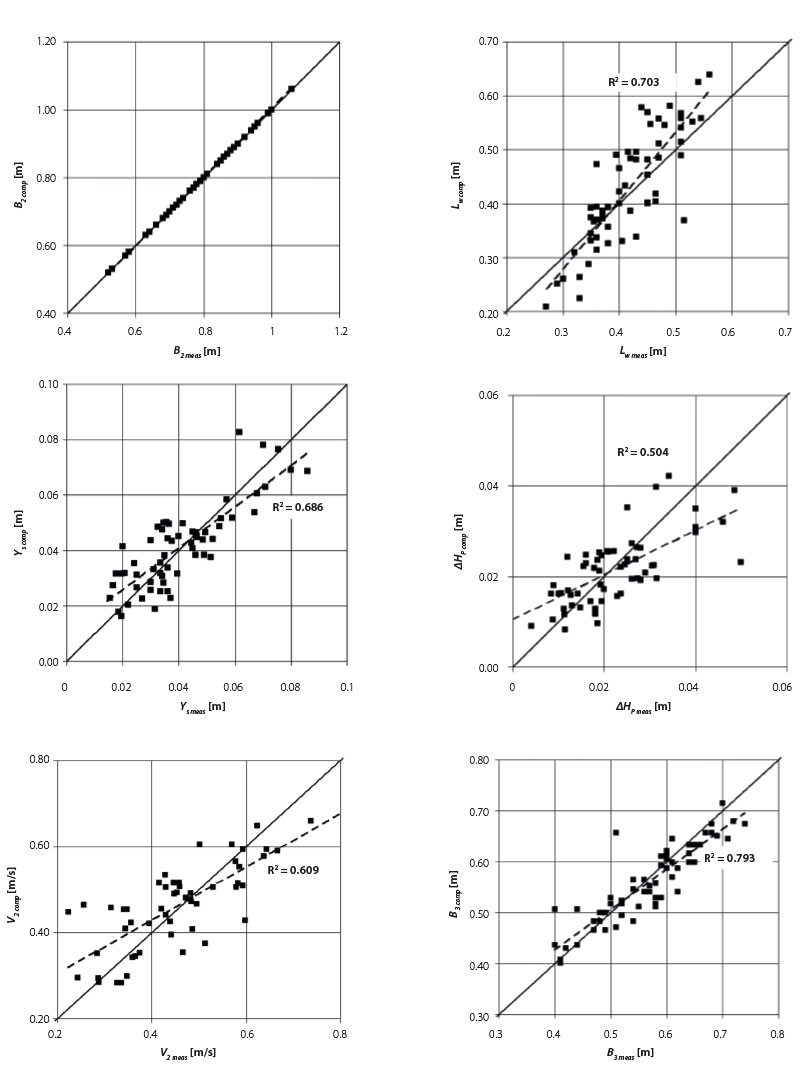
Fig. 7. Assessment of the scour hole computation methodology suitability by testing the agreement between calculated (comp) and measured (meas) geometric and hydraulic characteristics when selecting the width B2
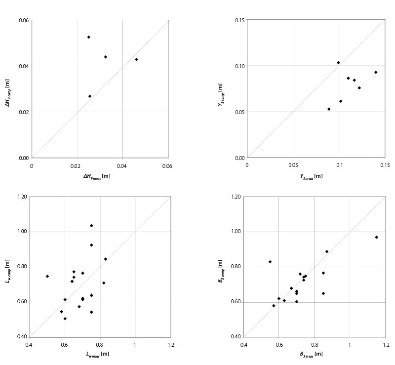
Fig. 8. Visual assessment of the “pear” scour hole computation methodology (when B2 is given) by scatter plot between computed data and measured data in the “full” 3D model
The procedure for assessing “closeness” was as follows. It was based on known data on the flow on the inlet profile to the scour hole (cross-sectional velocity V1, depth H1, and stream width B1 and the value Fr1 determined from them) and geomechanical properties of the soil (d50, ϕ) – these data will also be known in practice. Individual procedures were applied depending on which of the dimensions B2, Ys, or Lw was chosen as the starting point for the calculation. The result was the calculated quantities B2, Lw, Ys, ∆HP, V2, B3 (marked with the index comp = computed). These were compared with the quantities measured in the half-channel model (indicated by the index meas = measured) using a scatter plot. Fig. 7 shows the results of the scatter plot for the calculation with the selected dimension B2. The first graph of the set shows a complete match, since the targeted data was also used as the starting dimension in the calculation. The scatter plots performed for the other selected default scour hole dimensions Ys a Lw (not shown) allow us to conclude that the calculation methodology of the scour hole is the “closest” if the scour hole width B2 is used as the default selected dimension for the calculation.
In addition to assessing the “closeness” of the proposed computation methodology, its verification was also performed with a group of independent data obtained on a “full” 3D model. From the set of 23 experiments on the 3D model, it was possible to evaluate only some assessed quantities with a frequency of values in the set in the range of 4–17. This comparison between the computation methodology derived on the “half” model and the data found on the “full” 3D model is useful (Fig. 8). It can be determined here how significantly the simplifying assumption of flow symmetry in the scour hole is reflected in the correctness of the calculation methodology derived under simplified assumptions.
There is little data for comparison. Those that were available show that the simplifying assumption of symmetry does have some impact on the accuracy of the proposed “pear” scour hole calculation methodology when applied to the full 3D scour hole. However, it can be assumed that the influence of the correctness of the calculation methodology due to the assumption of flow symmetry does not exceed the influence of other factors, including measurement errors. For example, the vertical velocities determined in the “half” model were measured in a simplified way, and the glass wall in the stream axis apparently slightly influenced the shape of the surface and bed in its vicinity. In contrast, with the “full” model, there was a less accurate and time-consuming measurement of the bed and the level with a tip scale. When considering all the mentioned influences included in the framework of errors and distortions in the chosen procedure of experimental work, it can be assumed that the presented calculation methodology has a real base and could be beneficial in the field of design of morphological objects during watercourse restoration.
CONCLUSION
The above-mentioned procedure for designing a 3D scour hole depression in flow opening can be used in the design of small, environmentally acceptable watercourse channels or in the process of restoration of insensitively channelized small upland watercourse channels. The construction of pre-created morphological objects in the form of transition from fixed to lose perimeter of channel boundary, which support the creation of spatial flow and the dissipation of excess kinetic energy, can be a useful and cost-effective measure in the prevention of destructive erosion by flood flow in the river channel, and at the same time can lead to an increase in morphological and therefore habitat diversity within the watercourse channel.
However, the adoption of these measures as part of the process of river channel restoration must always be properly assessed by the relevant water authority from the point of view of the change in the condition and use of the actual watercourse channel and the area around the watercourse; for example, a fixed ameliorated drainage channel changes to an open shallow meadow stream and the surrounding drained agricultural area will be transformed into occasionally inundated meadows.
Acknowledgements
The article was created as part of the implementation of the project supported by the Technology Agency of the Czech Republic SS02030027 “Water systems and water management in the Czech Republic in conditions of climate change (Water Centre)”.
This article was translated on basis of Czech peer-reviewed original by Environmental Translation Ltd.
DOI: 10.46555/VTEI.2023.07.002
